I am not taking pictures of EVERYTHING I do because I am assuming that is you are planning to do this yourself you have the mechanical ability to figure things out. Thanks.
Lessons Learned:
- Always have enough supplies, i.e. electrical tape! I had to stop because I ran out and that will really bug you when something trivial like that stops you from continuing.
- Buy a SHOP MANUAL! The Haynes SUCK. They have not helped AT ALL. If you don't want to buy a manual make sure you have someone to contact about what wires are where, but hopefully this site will help.
- Be VERY CAREFUL when stripping wires! Even if you strip them perfectly, when you twist them together with the Haltech wire the old wires may BREAK! I had this happen to one of my stock injector plugs so now I can't put it on so I am ordering some new RC Engineering 800cc secondaries:>)
- You MUST have a VERY SOLID TPS bracket! If it flexes at all it will harm drivability. I made my current one out of thin steel but I will have to remake another at a later date due to a small amount of flexing.
- You WILL have some tuning issues when running in different temperatures that will need to be straightened out.
Grocery List:
- 9 pin male to female communications cable
- 10 feet of each different colored 14 gauge wire. I used remnants from stereo installs but it would work better if you had black, red, orange, gray, and maybe a few others.
- Electrical tape, A LOT!
- Spade connectors, the ones that take an existing wire and let you connect one by placing it in the connector and squishing it together.
- An electronic or analog multimeter
- A 3/8 NPT tap. This is a very confusing one and would be easier to find a nice machine shop that will do it for you, like Supreme Tool in Fridley, Minnesota. Had to give them credit because they were so nice.
- A good wrench set. I have a Craftsman 100 piece set and it works great.
- Assorted pliers, wrenches, etc..
- 1/4" hard plastic piece or something like it with 8" by 10" dimensions.
- More than 10 6mm bolts, some short some long, lock nuts, washers
- New water pump gasket and gasket from water pump housing to engine block.
- Laptop computer. Pretty much anything running dos will work.
- Shop towels, plenty of them.
- Sears rotary tool, Dremel, or anything that can cut plastic but you will use the rotary tool many time for other things and they are only 50 or 60 dollars.
Procedure:
Preparation:
- On my car the front clip is very easy to remove and it makes life a whole lot easier.
- Remove the intercooler.
- You may not HAVE to remove the radiator but it will make life a whole lot easier.
- Remove intake.
- Remove coupler, BOV, etc. above the turbo compressor.
- Unplug all hoses and connectors going to the TB.
- I have the TB mod which simplifies things but now remove the VDI and TB all in one piece.
- Remove the pressure sensor on the strut area.
- Remove the alternator.
- Unplug the fuel injectors and the two water sensors just below the thermostat. The lower one is for the AC. It is better to remove this one rather than the top one, which is the water temp sensor. The lower one will be easier to tap.
- Remove the air conditioning components. This is an optional step but it gave me a much larger area in which to create a mounting plate for my Haltech and also gave me three holes through the firewall.
- I made a plate for my Haltech and Greddy unit to attach onto. I used 1/4" stiff plastic. I happen to have some in my basement which is white and very stiff. I measured out an 8" by 10" area and then cut it with my Sears rotary tool.
- At the top of the 8" side there needs to be two holes 4 1/4" apart. I placed the first one 1" in from the side and 1/2" down from the top. This way it will fit where the top two screws for the condenser used to go.
- It would be wise to print out or have a computer on hand to display the following website. Here is what I did:
Routing Wiring Loom:
- Send only the following wires through the firewall; TPS, MAP, Injector, water temp., air temp., ignition, and Trigger using the top hole of the AC. I was able to fit all of the plugs with the exception of the ignition and TPS. I cut the TPS and then put it back on and since you will need to cut the ignition plug off anyway, it was no problem.
- I used a wood 1 1/4" drill bit to make a hole in the back of my glove compartment where the fuse block and com cable will be mounted. I then drilled two holes for the fuse block to mount onto and then used two long 6mm bolts with a washer and locknut on the other end.
Trigger:
- Now I routed the Trigger plug (the one with 6 wires and 4 of them are shielded with a gray cover) to the CAS (Crank Angle Sensor) to make sure it reached, it did. Now I cut the CAS female end off of the main wiring loom in order to splice it together with the Trigger input. Follow the wiring directions on The Hitman's page. You don't need hook up the other two wires.
- In order for the timing to work you must take out the crank angle sensor and point the top at the two cover screws as The HITman states. All you do is take off the cap, unscrew the 2 big screws by the multi tooth wheel, unscrew the bolt on the power steering side of the crank angle sensor and then pull upward. It will pop out so pull carefully. Now you can place it in as close as you can so it is pointing toward the two cap holes and then you can adjust it by twisting the crank angle sensor top when it is in. It sounds confusing but it is very easy.
Tapping and Mounting Sensors:
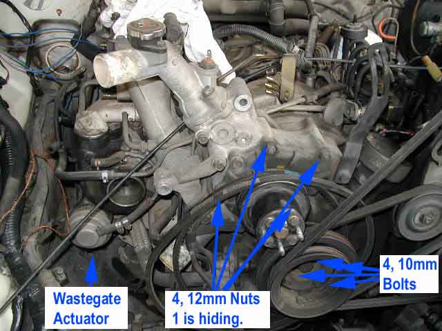
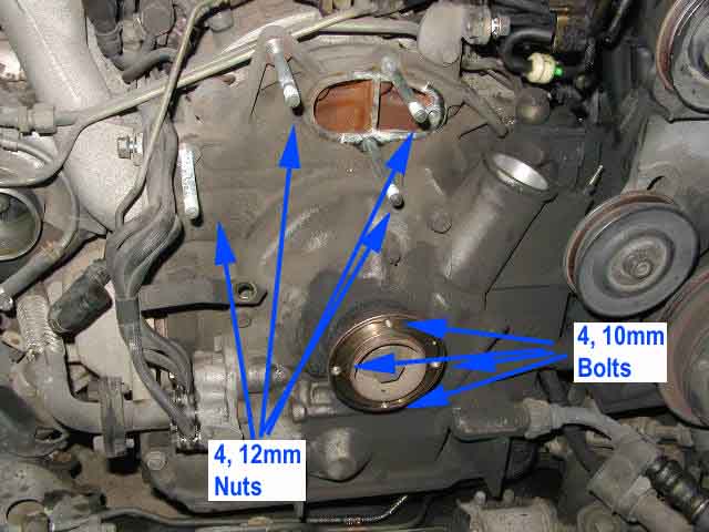
- Picture 1, Picture 2 See picture 1 for the before shot of the water pump housing still attached and picture 2 for the after shot of the housing removed.
- In order for a good tap for the sensors you should pull off the water pump housing and the intake pipe that has the air sensor in it. Pulling off the water pump housing should be pretty easy and the intake elbow is cake. I tried the 4 10mm bolts but for the life of me it would not come off so I had to do it the hard way, which is further on in the paragraph. First try hitting the pullies with a rubber hammer when the 4 bolts are out and they should drop off, Arturo did this with good results. If your last resort is to pull the housing because the main pulley didn't come off then read on. To remove the housing you will notice that there are 4 nuts to unscrew and 3 bolts. The bolts are what hold the water pump to the housing and the nuts hold the housing onto the engine block. To remove the studs take a big vice grip with some rubber pieces over the jaws, I used bicycle tires. CAUTION: DOING THIS MAY RUIN THE STUDS AND YOU WILL HAVE TO BUY NEW ONES. With the studs removed you can take the water pump housing off, you just have to remove the BAC hose and some other hose near the bottom of the housing. I found some generic bolts to replace the studs at my Mazda dealer with the correct pitch and cut them to size which works great.
- When I re-installed the water pump and housing I used my rotary tool with a sandpaper bit to sand off the old gasket. This makes for a very smooth fitting for the new gasket.
Ignition:
- Well, last night the great people of RX7.com, especially Ari, helped me out with the ignition wiring and I will help you now. The ignition wire loom is the one with 6 wires going into a big flat plug. You will need to cut off the plug in order to thread it through the firewall but since you don't need the plug what does it matter. Strip the Green with black stripe, Light Green, and White with Black stripe. Now go to the LEADING igniter, the one by the battery. You should see a white plug with two wires going in (two black ones with colored stripes), and two coming out (a TAN and a PINK), snapped onto a piece of metal near the igniter. My colors were kind of faded but I could tell between the pink and tan enough to get them right. You will need some extra wire to reach both igniters, I just used speaker wire. Now wire together the following wires but you have to make sure they are ONLY connected to the Haltech and do not continue on to the ECU:
- The trailing igniter is easiest to access if you unscrew it and lift it out. With it lifted up you will see a four wire plug with the Pink and White wires along with two others. The other two are for power so leave them alone. Now wire together as above and remember that they have to ONLY go to the Haltech and not continue to the ECU.
Fuel Pump:
- Pop the hatch and pull up the carpeting and sound damping so you can access the fuel pump. You will also need to pull back the side flashing so you can unplug the fuel pump.
- Take out the rear carpeting along with the storage bins (Optional). To do this you just pull the carpet up as much as you can and then unscrew the snaps using a Phillips screwdriver. Once you have those out you will see 5 bolts going down the middle of the storage holes. Take those out. Also take out the 5 bolts that hold the fiberglass to the frame behind the back seats.
- Now you can rewire the fuel pump. Unplug the pump from the driver's side shock tower and cut the 2 thicker BLACK wires about 3 inches down from the plug that went to the shock tower. This is where you will splice in some wires. There are two ways to wire the fuel pump, one is to use the existing power wire, which sounds dumb, and the other is to use a bigger power wire, the better way. Run one orange wire from your Haltech up to the battery and put a circular terminal on it so it can attach to the battery. Now run the other orange wire down the side of the center console so it reaches close to the fuel pump. You will need to get some 14 gauge wire to make it fit. This wire will attach to the BLACK WITH WHITE STRIPE, that is the power. The other BLACK wire is ground. Ground it somewhere. That's it. Just plug it back in and the fuel pump is done.
Injectors:
- Since I screwed up my injector plug when trying to splice it in with the Haltech, I ordered 2 RC Engineering 800cc injectors to put in the secondaries. I figured I would need them later anyway and then I can use the better plugs that came with the Haltech.
- To install the two injectors was very easy. CAUTION: GAS IS EXTREMELY FLAMMABLE SO BE CAREFUL! When you pull out the injectors, be sure to have some towels underneath to catch the gas that WILL SPILL OUT. The one close to the front of the car had to be plugged in with the plug coming out of the side behind the fuel line rather than the stock location because it would not fit. The other injector was fine.
General:
- The 6 wires need to be wired to the following:
- Black=Battery Negative
- Red=Battery Positive
- Grey=12V while cranking and when On (Best place is where trailing igniter gets it's power which is from either of the two wires that plug into the igniter).
- Green=Don't need. This is for accessories like NOS
- Orange=Battery Positive
- Orange=Fuel Pump Positive
- Now that everything is wired triple check that everything is plugged in and put the car back together enough to run it. You don't need the hood or anything. If you are confident that everything is plugged in you can plug the main loom into the Haltech. Now turn the key to the On position and see if you hear the fuel pump prime. It is an electrical humming noise that occurs for about 2 or 3 seconds. That is good if you hear that.
Computer:
- The last thing you need is a notebook computer. I am using a Compaq Pentium 120 running Windows 95, but all you need is pretty much ANY notebook with a com port because if you look at the requirements you will see that it can run on a 386 dinosaur. They are coming out with a Windows program soon though.
- Plug the com cable in and power up your computer. All you need to do is copy all of the contents of the disk onto your C: drive, drag and drop works fine, and then run the program. I was having troubles with my computer not communicating with my Haltech but I went into my com port settings and set it to No Caller Access. This will be different on all computers but if when you boot up Haltech and try to go Online it just sits there, you have a com port problem.
- I used one of The HITman's maps and after some cranking it fired up and idled SMOOTHLY!!!!!! I haven't had a smooth idle since I bought the car because of that stupid TPS. You may idle high so just back out your idle set screw but I have mine all the way out and still idle high so I am going to get rid of my BAC valve as soon as I can get someone to make a block-off plate. You no longer need that thing, YEA!!!
If you have any questions, go to my home page and e-mail me and I will respond a.s.a.p..
Eric Moreira